ULTRASONIC FLAW DETECTOR
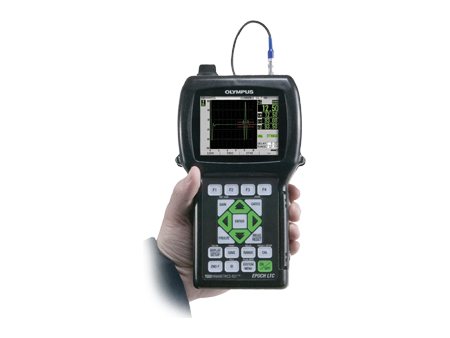
EPOCH LTC
Rugged, Handheld Flaw Detector
Features
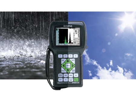
■ Designed for IP67 rating to ensure field ruggedness
■ Complies with the EN12668-1 standard
■ Only 960 g (2.1 lb)
■ Full-color VGA display with transflective technology
■ USB On-The-Go port for computer communication and direct printing
■ Onboard and miniSD Card storage capabilities for the data logger
■ Standard dynamic DAC/TVG
■ Standard onboard DGS/AVG
■ Digital high dynamic range receiver with digital filters
■ High-performance square wave pulser with tuning option
| General | EN12668-1 Compliant | |
|---|---|---|
| Weight | 2.12 lbs (0.96 kg) with Li-ion Battery | |
| Dimensions | 8.79″ H x 5.07″ W x 2.17″ D; 223.3 mm x 128.9 mm x 55.1 mm | |
| Keypad | English, International, Japanese or Chinese | |
| Languages | English, Spanish, French, German, Italian, Japanese, Chinese, Russian, Norwegian, Swedish | |
| Transducer Connections | LEMO 00 | |
| Battery | Rechargeable Lithium Ion. Pack for AA cells standard | |
| Battery Operating Time | – Lithium Ion Rechargeable Pack: 8 hours – AA Lithium Ion Cells: 6 hours – AA NiMH Cells: 4 hours – AA Alkaline Cells: 3 hours |
|
| Power Requirements | AC Mains 100-120 VAC, 200-240 VAC, 50-60 Hz | |
| Environmental Ratings | IP67 Environmental Ingress Protection Rating | |
| Explosive Atmosphere approved per | MIL-STD-810F, Procedure 1, NFPA 70E, Section 500, Class 1, Div. 2, Group D Shock Tested per: IEC 60068-2-27, 60 g, 6 msec H.S., 3 axes, 18 total | |
| Vibration Tested | Sine Vibration per IEC 60068-2-6, 50-150 Hz @ .03″ DA or 2 g, 20 sweep cycles | |
| Drop Tested | MIL-STD-810F 4.5.5 Procedure IV – Transit Drop | |
| Display | Color Transflective Liquid Crystal Display | 60 Hz update, user-selectable color schemes and brightness, two split screen modes and one full screen mode. |
| Display Dimensions | 640 Pixels (W) x 480 Pixels (H) 2.95″ W (75 mm) x 2.21″ H (56 mm), 3.7″ (94mm) diagonal | |
| Amplitude Grid Modes | 100% or 110% Amplitude Display | |
| Time Base Grid Modes | Standard 0 to 10 division, Soundpath Mode divides Range into 5 equal sections with grid lines, Leg Mode displays Soundpath Legs as grid lines | |
| Pulser | Square Wave Pulser | Fixed width square wave pulser optimized for general flaw detection applications. |
| Pulse Width | Fixed Width in Base Instrument. Adjustable from 45 ns to 5,000 ns (0.1 MHz) with EPLTC-SWP Option | |
| Pulse Repetition Frequency (PRF) | Automatically controlled by the instrument software over the range of 10 Hz to 500 Hz. Manual PRF control option available (PN: EPLTC-PRF) | |
| Measurement Rate | 10Hz to 500Hz. Always equal to PRF rate. | |
| Energy Settings | 100 to 400 V in 100 V increments | |
| Damping | 50, 100, 200, 400 Ohm | |
| Receiver | Gain | 0 to 110 dB – Two user-defined gain step adjustments and presets above function keys |
| Total Instrument Bandwidth | 0.2 – 26.5 MHz @ -3 dB | |
| Digital Filter Settings | Standard: 0.2 – 10.0 MHz Broadband: 2.0 – 21.5 MHz High Pass: 8.0 – 26.5 MHz |
|
| Rectification | Full-wave, Positive Half-wave, Negative Half-wave, RF | |
| System Linearity | Horizontal: +/- 0.5% FSW | |
| Resolution | 0.25% FSH, Amplifier Accuracy +/- 1dB | |
| Reject | 0 to 80% full screen height with visual warning | |
| Calibration | Automated Distance Calibration for Velocity and Zero Offset | |
| Test Modes | Pulse Echo, Dual, or Through Transmission | |
| Units | Millimeters, inches, or microseconds | |
| Range | Base Instrument: 3.36 mm to 6,702 mm (0.132 in. to 263 in.) at 5900 m/s (0.2320 in./ms) | |
| Extended Range Option | (PN: EPLTC-RANGE): 3.36 mm to 13,404 mm (0.132 in. to 527 in.) at 5900 m/x (0.2320 in./ms) | |
| Velocity | 0.025 to 0.6000 in/µsec (635 to 15240 m/S) | |
| Zero Offset | 0 to 750 µsec | |
| Display Delay | -2.323″ to Max Range (-59 mm to Max Range) | |
| Refracted Angle | 10° to 85° in 0.1° resolution | |
| Measurements | Types | Thickness, Soundpath, Projection, Depth, Amplitude, Time-Of-Flight for Gate 1, Gate 2 – Gate 1 |
| GATE 2 option | (PN: EPLTC-GATE2): Allows Echo-to-Echo measurements independent of Gate 2 measurements, and Gate 2 alarms. | |
| Four Measurement Display Locations | User selects up to four measurements from either gate to display on the live screen. | |
| Dynamic DAC/TVG Standard | ASME, ASME III, JIS, and CUSTOM DAC with up to six warning curves. Allows dynamic adjustment of curves with Gain, Dynamic range 110 dB, Slope 100 dB/usec and up to 50 points captured. | |
| Amplitude Measurement | 0 to 110% full screen height | |
| X-Value Correction | Removes distance from Beam Index Point to front of transducer from surface distance measurement. | |
| Gate 1 | Measurement of Echo Height and Time-Of-Flight. | |
| Gate Start | Variable over entire displayed range | |
| Gate Width | Variable from Gate Start to end of displayed range | |
| Gate Height | Variable from 2 to 95% full screen height | |
| Alarms | Positive and Negative Thresholds; Minimum Depth | |
| Zoom | Displayed Range is Gate 1 Width. |

 Korean

